 Introduction Introduction
 |
|
Saturated/unsaturated seepage analysis program using Finite Element Method
(FEM) is based on the analysis solver produced by the Prof. Ugai laboratory
(Department of engineering, Gunma university). This product has been developed
by customizing VisualFEA as pre and post parts. It provides easy ways to
generate two and three dimensional (2D and 3D) complicated shaped geological
boundary models, and several functions such as regular meshing, auto-meshing
and re-meshing by setting types and dimensions of elements. Stationary
and transient analysis can be conducted in 2D vertical, 2D axisymmetric,
horizontally 2D and 3D models using several boundary conditions.
|
|
 Functions and features Functions and features
 |
 |
Analysis Type
Steady flow analysis / Transient flow analysis
Analysis Model
# 2D horizontal plane flow model
# 2D vertical plane flow model
# Axisymmetric flow model
# 3D flow model
Node configurations
| |
1st Element : |
3-node triangle element / 4-node quadrilateral element / 4-node tetrahedron
element / 6-node prism element / 8-node hexahedron element |
| 2nd Element : |
6-node triangle element / 8-node quadrilateral element / 10-node tetrahedron
element / 15-node prism element / 20-node hexahedron element |
Initial-condition
# Pressure head is supposed to be linearly distributied
# The table input of the pressure head
# Water content by volume is supposed to be linearly distributed
# The table data input of the Water content by volume
Boundary Conditions
This product can define the following six types of boundary conditions and set fluctuating water level and rainfall boundaries at the same time.
# Known hydraulic head
# Flux
# Potential seepage face
# Outflow forbidden
# Fluctuating water level
# Rainfall
Unsaturated seepage characteristics
van-Genuchten model / Direct inputs of Volumetric water contents - Suction and Volumetric water contents - Relative hydraulic conductivity
Output items
# Total head
# Flow rate
# Water content
# Pore water pressure
# Current speed of x direction / y direction / the z direction
# Current speed vector
Output capability
As following, there are various drawing function of result analysis. This allows user to understand the status of flow visually, be able to cut and rotate the cross section of 3D model.
# Contour figure
# Iso surface figure (Equivalence curved surface figure)
# curve plot (Graph display of contour value)
# surface figure (Display of contour distribution as curved surface)
# groundwater graph
# flow line graph
# the flow value of any specified cross section
# specified nodal value
Applicable scope
1. Influences of rainfall and spring in large basin
2. Measures of seepage surface and water pressure distribution in river levee,dam and reservoir
3. Design calculation of fill type dam body and investigation of seepage on the ground aruong reservoir
4. Simulatio of water pressure in reservoirbed and foundational ground around reservoir for disaster prevention
5. Examination of piping and boiling during excavation
6. Influences of confined groundwater
7. Effect of drainage well on pore pressure distribution in landslide region
8. Investigation of seepage in cofferdam
Applied standard
"Construction Ministry, Technical Criteria for River Sand Control Works : Practical guide
for Design[I] (Draft plan)" -Sankaido Publishing Co., Ltd
"High-Standard Bank Embankment Design and Enforcement Manual" - Foundation for
River front Improvement and Restoration
"River Bank Structure Guideline", -Japan Institute of Construction Engineering
"All-purpose Dam Construction" - Japan Dam Engineering Center |
Page Top  |
|
 Pre-post-section Overview Pre-post-section Overview |
 Introduction Introduction
 |
 |
This product is a pre-post version of 3D seepage analysis (VGFlow), and can be used as general-purpose finite element model creating tool by using powerful mesh creating function. |
|
 Functions and features Functions and features
 |
 |
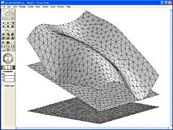
Plane mesh creating of terrain / layer based on DEM data
Plane mesh of terrain / layer based on DEM data can be created after creating fundamental plane mesh by using projection function of datum plane mesh.
 
Plane / solid mesh edit with Boolean operation
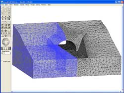
Plane mesh, solid mesh can be edited by using the divide function of crossing part on plane mesh, a Boolean calculation function, the cutting function of solid mesh, after creating mesh.


The setting of material parameter and the boundary condition
Material parameter or boundary condition can be set for a made finite element.
 
The optimization of the finite element data and textual output
The following finite element data can be file- exported as text format, optimizing the order of node number/ element number of the created finite element model.
# Node data(a coordinate, a boundary condition)
# Element data(an element type, property number and node number)
# Material data (material parameter)
# Other data (corresponding to known hydraulic head boundary condition of the seepage analysis)
Post-output capabilities
FEM analysis can be used for the evaluation of 3-dimentional area from many directions with various post-outputs of contour figure, iso-surface figure, groundwater graph, vector diagram, and flow by cross section graph, numerical confirmation. |
Page Top  |
|