New Products
Engineer's Studio® Ver.6
3D plate dynamic non-linear analysis

●Price Ultimate: US$19,200(SS: US$2,880)
Ultimate (Not including the Maekawa model): US$12,300(SS: US$1,845)
Ultimate (Not including the Cable Element): US$15,900 (SS: US$2385)
Advanced: US$8,400 (SS: US$1,260)
Lite: US$5,700(SS: US$8,550)
Base: US$3,690 (SS: US$590)
●Released date
September 12, 2016
FEM Analysis
 Introduction
The following features have been added for Engineer's Studio® Ver.6.
  • A triangular 3 node plate element has been added.
  • A quadrilateral 4 node plate element has been improved.
  • Expansion of tension softening coefficient C of the non-linear RC plate element
  • A function to convert high order elements to their corresponding low order elements
  • A new feature was added to permit the setting of group membership for a set of selected elements and/or nodes.
  • Input waveform is now displayed on the result of the dynamic analysis.
  • Sample files and help information were added for push over analyses.
 Addition of a triangular 3 node plate element
Because triangular 3 node element could not be used until now, quadrilateral 4 node element and triangular 3 node element could not be mixtured when auto-mesh dividing complex shaped area. It is now possible due to the addition of triangular 3 node element (refer to Triangular Linear in Fig. 1). Triangular linear element is based on literature [1] and [2].
  • Literature [1] Long Yuqiu, Xu Yin, Generalized conforming triangular membrane element with vertex rigid rotational freedoms, Finite Elements in Analysis and Design, Volume 17, Issue 4, 1994, Pages 259-271.
  • Literature [2] Soh. A., Long, Z.F. & Cen, S., 1999, A new nine DOF triangular element for analysis of thick and thin plates. Computers & Structures, 24,408-417.
 Improvement of a quadrilateral 4 node plate element
Addition of a triangle primary element enables a mixture of 3 and 4 node elements during the automatic mesh of complex shaped field. Kind of flat plate elements including new triangular 3 nodes element are below (Fig. 1, Fig. 2).
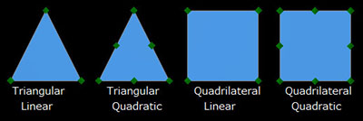
 ・Triangular 3 node element and a primary form function
 ・Triangular 6 node element and a secondary form function
 ・Quadrilateral 4 node element and a primary form function
 ・Quadrilateral 8 node element and a secondary form function
Fig. 1 Kind of flat plate elements
  • Literature [3] Soh, A., Cen, S., Long, Y. & Long, Zh., 2001, A new twelve DOF quadrilateral element for analysis of thick and thin plates. Eur. J.Mech. A/Solids, 20, 299-326.
Fig. 3 is an example of auto-mesh divide with the mixture of square and triangular primary element.

Fig. 2 Three types of creation commands
for plate elements
Fig. 3 Auto-mesh divide with the mixture of square
and triangular primary element
 Expansion of tension softening coefficient C of the non-linear RC plate element
The input for the reinforcing in plate sections was improved. It was not possible to define Cx and Cy (tension softening parameter) independently for each axis for unreinforced concrete. Also it is now possible to use an automatic method for calculating C. Improvements to the layout and input forms have also been made. It is now clearer which parameters are required in different configurations. (Fig. 4)
Fig. 4 Input of plate section
 A function to convert high order elements to their corresponding low order elements
A function was added to convert 6 & 8 node (high order) elements to their corresponding 3 & 4 node (low order) elements. The conversion feature can be used when the intermediate node is not used as supporting point and is attached to no other elements. (Fig. 5)
Fig. 5 A button to convert high order elements
to low order elements
A feature to permit the setting of group membership for a set of selected elements and/or nodes
A command to select multiple nodes and elements, and edit its group has been added (Fig. 6).
Fig. 6 Edit group membership
 Input waveform display on the result of the dynamic analysis
A button to call up input seismic wave form when checking time history result of dynamic analysis has been added. When pressing the button, a window of input wave will be displayed. Clic in the wave form graph to move on to the next step, and deformation diagram and sectional force diagram of models are synchronized to ones in the step then (Fig. 7).
Fig. 7 Input wave on time history result
 Addition of sample files and help information for push over analyses
Sample files were added for push over analysis (Fig. 8, Fig. 9, Fig. 10).
Refer to Engineer's Studio® Help | Technical note | Pushover. The samples are considered by comparing several ways for creation of load displacement curve. The following 3 sample data are available.
 ・Pushover-Rahmen-Case1.es
 ・Pushover-Rahmen-Case2.es
 ・Pushover-Rahmen-Case3.es
Fig. 8 Pushover analysis model
Fig. 9 Deformation diagram
of pushover analysis
Fig. 10 Relations between load displacements of pushover analysis
(Up&Coming 2016 Fall Issue)
Back
Up&Coming

FORUM8