| Support Topics | ||
| Support Topics / FEM Engineer's Studio® | ||
|
||
|
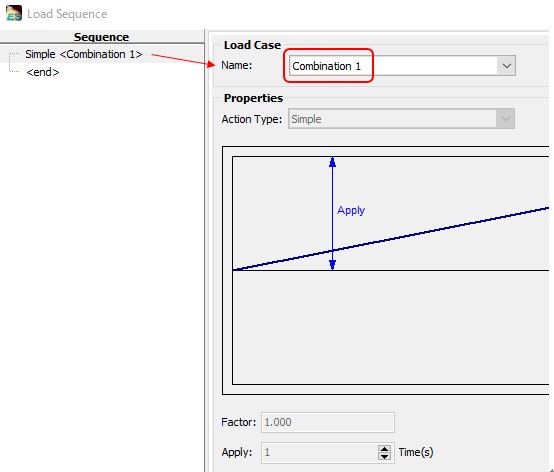
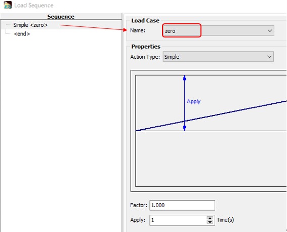
When you model PC members with M-φ elements and give initial cross-sectional forces determined separately to it, you have to enter the total of the primary and secondary forces due to prestressing and all other loads as an optional setting. To validate this input method, we will compare it to the conventional method that does not use initial cross-sectional forces (the primary force and dead load due to prestressing are given at one step of sequence loading) to find that values match. Analysis Model A simple beam 30 m long is divided into 10 sections (Fig.1). Each member will have PC steel (effective prestress = 891.424 N/mm2) (Fig.2). Fig.3 and Fig.4 show the run setup. Run1 (non) is the conventional method. The combined load, including dead load and pre-primary, is loaded in one step (Fig.5). Run2 (ISF) is a run that takes into account the dead load and pre-primary in the initial sectional force. The loading in the one-step is an empty load (zero load) (Fig.6). Result Bending moments are almost identical with and without initial cross-sectional forces (Fig.7 and Fig.8). Consideration When modeling PC members with M-φ elements, the following procedure is used. 1) Set primary and secondary forces and all other loads to initial cross-sectional forces (input by optional settings) 2) Place PC steels with effective prestressing in the cross section. 3) M-φ characteristics are automatically created from its cross section. 4) In the M-φ setting, select "From Initial State" for Axial force N' setting. 5) Apply dynamic load to sequence load from the step 1. 6) Put a check in "Use Initial Element Force in Run" in the initial state setting screen. |


