ENSOFT havs cutting-edge civil engineering applications such as LPILE Plus
v5.0, GROUP v7.0. This time FORUM8 will distribute these 2 applications,
LPILE Plus v5.0 and GROUP v7.0. Product overview is as following.
LPILE Plus is a special-purpose program based on rational procedures for
analyzing a pile under lateral loading.
The program computes deflection, shear, bending moment, and soil response
with respect to depth in nonlinear soils. Components of the stiffness matrix
at the pile head may be computed internally by the program to help the
users in their super-structure analysis. Several pile lengths may be automatically
checked by the program in order to help the user produce a design with
an optimum pile penetration. Alternatively, the user can manually introduce
other p-y curves. Special procedures are programmed for developing p-y
curves for layered soils and for rocks. Several types of pile-head boundary
conditions may be selected, and the properties of the pile can also vary
as a function of depth. LPILE Plus has capabilities to compute the ultimate-moment
capacity of a pile's section and can provide design information for rebar
arrangement. The user may optionally ask the program to generate and take
into account nonlinear values of flexural stiffness (EI) which are generated
internally based on specified pile dimensions, material properties, and
cracked/ uncracked concrete behavior.
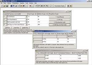
 Sample screen Sample screen |
|
p-y curve output example |
 LIST OF FEATURES LIST OF FEATURES
|
Five sets of boundary conditions are available to model the pile head:
free head, pinned head with sway, fixed head with sway, or elastically-restrained
with a rotational spring. Depending on boundary conditions, pile-head loading
may consist of a lateral load, a bending moment, a specific lateral displacement,
or a specific pile-head rotation. The ability to specify both deflection
and rotation at the pile head is an useful feature available in LPILE Plus. |
|
The user may optionally ask the program to generate and take into account
nonlinear values of flexural stiffness (EI). These values are generated
internally by the program based on cracked/uncracked concrete behavior
and user-specified pile dimensions, and material properties. Version 5
allows the user to define multiple sections with nonlinear bending properties. |

LPILE Plus model of soil response
Sample results from push-over analyses |
|
Up to ten different load cases may be applied at the pile headin a single
analytical run. This is a helpful feature for the quickobservation of pile
behavior subjected to specific increments of lateral loads, bending moments,
lateral displacements, o rpile-head rotations. |
|
A set of distributed lateral loading may be applied anywhere along the
length of the pile. Loading may be specified as constant or varying linearly
with depth. |
|
Four values (Kyy, Kyθ, Kθy, and Kθθ) of a typical 6x6 matrix for foundation
stiffness may be generated by the program for a range of loading. Values
are helpful as nonlinear foundation models in superstructure analysis. |
|
An user-specified curve may be used to model the additional shear resistance
provided by the soil at the base of large-diameter drilled shafts and/or
short piles. |
|
LPILE Plus has the capability to perform push-over analyses and can study
the pile behavior after the development of plastic hinges (yielding). |
|
Several pile lengths can be automatically checked by the LPILE Plus program
in order to help the user produce a design with an optimum pile penetration. |
|
Soil-resistance (p-y) curves can be internally generated by the program
for the following soils: soft clay, stiff clay with or without free water,
sand (Reese et al), sand (API), silt (c-φsoils), liquefied sand, strong
rock, and weak rock. |
Example of Calculation Result
| ・ |
Users may optionally input their own soil-resistance (p-y) curves for certain
soil depth |
Sample set of curves of bending moment
versus depth for different lateral loads |
| ・ |
A special subroutine effectively incorporates the infuence of layered soils. |
| ・ |
User-defined multipliers are provided to increase or reduce the soil resistance
(p-y curves) at any points along the length of the pile. This feature is
used in seismic conditions to reduce the response of liquefied layers or
to account for Group Effects. |
| ・ |
Linear interpolation of bending stiffness is computed for piles with varying
cross sections. |
| ・ |
The Graphics menu contains quick observations of results contained in the
output file (variations of pile deflection, bending moment, shear and soil
resistance with pile depth). The user can customized charts to prepare
various engineering plots in high quality for presentation and report. |
A Progam for the Analysis of Pile in a Group
GROUP has been well accepted as a valuable design tool for analyzing the
behavior of pile in a group subjected to both axial and lateral loadings.
The program computes the distribution of loads (combination of vertical,
lateral, and overturning moment in up to three orthogonal axes) from the
pile cap to piles arranged in a group. The piles may be installed vertically
or on a batter and therir heads may be fixed, pinned, or elastically restrained
by the pile cap. The program wil generate internally the nonlinear response
of the soil, in the form of t-z and q-q curves for axial loading, in the
form of p-y curves for lateral loading. The p-y, t-z q-w and t-r curves
may be generated internally ,emplyoing recommnendations in technical literature,
or may be entered manually by the user. The pile-head forces and movements
are introduced into equations that yield the behavior of the pile group
in a grobal coordinate system. The program can internally compute the deflection,
bending moment, shear, and soil resistance as a function of depth for each
pile.
3D model with GROUP V7.0 |
|
3-dimensional calculation |
LIST OF FEATURES
| ・ |
Three boundary conditions are available for pile-head connections to the
rigid cap: pinned, fixed, or elastically restrained. |
| ・ |
p-y curves may be input by the user or may be automatically generated by
the program and printed for review. |
| ・ |
This program can provide data for evaluating the pile-cap stiffness, often
uesd by structural engineers for foundation simulation in ther numerical
models. |
| ・ |
The graphical observation of output curves features a new interface that
allows zooming of areas of particular interest. The user may thus observe
the detailed behavioral measurements of any portion of the depth of each
pile sub-group. |
| ・ |
The type and number of graphs generated by GROUP v7.0 have been increased
over previous versions.
More importantly, the program plots the force and displacement on the pile
cap, such as the axial force (tension and compression) of each pile on
the pile cap, llateral forces (shear and moment) of each pile on the pile
cap, and the displacement of the pile cap in different directions. |
| ・ |
The program allows for up to 2000 piles in a group, and each pile can have
diffrent EI values in orthogonal directions. |
| ・ |
The program will consider the nonlinear bending stiffness(EI) of each pile
during computation. The user can enter nonlinear moment-curvature curves
under different axial loads for each pile. |
Program GROUP allows the input of groups of straight or batter piles, layered
soil profiles, various cross-section of pile sub-groups, and several loading
arragements |
|
Sample windows used for data input |
Moment distribution |
|
Moment distribution |
Moment distribution |
|
Moment distribution |
| Products name |
Price |
| LPILE Plus 5 for Windows (A Program for the Analysis of Pile and Drilled Shafts Under Lateral Loads) |
¥130,000 (tax excluded) |
| GROUP 7.0 (3-D) for Windows (A Program for the Analysis of Piles in a Group) |
¥200,000 (tax excluded) |
 Developed by ENSOF, INC.. : www.ensoftinc.com Developed by ENSOF, INC.. : www.ensoftinc.com |