| SUPPORT TOPICS | Question & Answer Forum - VR |
Maintenance/Support Service Related Information |
| UC-win/Road |
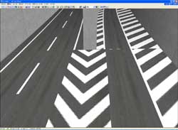
| A method of connecting a "right-turn" ramp and connecting ramps smoothly |
UC-win/Road only allows you to connect the ramp on the left-hand side of the driving lane.
We have received many enquires from our users, since the right-hand side ramps are not rare in such highway as the Tokyo Metropolitan Expressway and highways in other urban area.
We introduce two connection methods to connect ramps on the right-hand side
Method 1
The method of setting the main alignment as the 'right-turn' ramp
Set the 'right-turn' ramp as the main alignment and then connect the main road to the 'right-turn' ramp.
Method 2
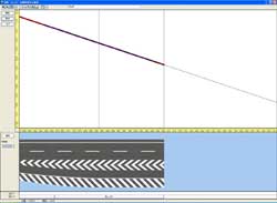
The method of connecting the main road with the ramp
Set an end point of the main road at the ramp connection, and then connect the main road with the ramp.
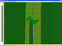
2. Tips for connecting the ramp smoothly
- Note the following when you connect a ramp including a 'right-turn' ramp
・ To make a ramp connection smooth, the y-coordinate of the road must correspond with the y-coordinate of the right-hand side of the road, just before the exit ramp, and also the slope of the exit ramp road must correspond with the slope of the road just before the exit ramp. In addition, make width of both lanes the same.
・ If you failed to connect a ramp, you can reconnect it by right-clicking on the triangle and selecting "Reconnect".
・ It may create spaces at the ramp connection. This is because the main road and the ramp of the road are not parallel to each other. To solve this, you need to adjust the plane IP or curvature or add curvature IP.
 |
 |
 |
Page Top

| SUPPORT TOPICS | Question & Answer Forum - Dynamic Analysis | Maintenance/Support Service Related Information |
| UC-win/FRAME(3D) |
| The property of the nonlinear element (1) |
There are three possible models when they are modelled in UC-win/FRAME (3D).
- A model that sets rotational plastic springs (M-θ property) in half-way point of the length of the plasticity hinge
- A model with a plasticity hinge area with a M-φ element
- A model with a plasticity hinge area with a fiber element (consideration for axial force variation, biaxial bending)
This time, we consider results of three models above
 |
For a comparison of above three elements, the same intersections and the same loads are given to draw "load-displacement curve".
 |
As mentioned in the previous issue, fiber elements have a minus curve in concrete hysteresis, so analysis by loadings can not be carried out after post-peak.
Therefore, loading by the displacement is carried out for this examination.
M-θ, M-φ are equivalent to each other and the result of the fiber elements seem to be estranged at first view, but yield displacement of the reinforcement and the ultimate displacement of the concrete become about the same
| M-Θ | M-φ | Fiber | |
| δy0(mm) | 18.5 | 19.5 | 20.0 |
| Py0(kN) | 743.2 | 782.3 | 821.1 |
| δu(mm) | 164.0 | 164.5 | 164.0 |
| Pu(kN) | 969.3 | 969.2 | 943.2 |
| δy(mm) | 24.1 | 24.2 | 23.0 |
| Py(kN) | 969.3 | 969.2 | 943.2 |
| a(---) | 1.5 | 1.5 | 1.5 |
| μa(---) | 4.865 | 4.873 | 5.093 |
| δa(mm) | 117.4 | 117.7 | 117.0 |
When an allowable displacement is calculated just as in the above table, these three elements become approximately equal.
In other words, three models give the same result as long as biaxial bending, axis power vibration do not occur in these models.
We are going to consider the case which biaxial bending occurs in the next issue.


