Support Topics
Support Topics / UC-win/Road
City Design tool Vol.5 ImageToFacade

I am Kobayashi of Arizona State University. I'll introduce the tool called CityDesign currently released from Forum8. I am aiming to the development of tool group for creating and converting the city data seamlessly between UC-win/Road which is the VR package of Forum8 and the other 3DCG package. The tool introduced here also exposes the source code. Since I haven't take a support so far, the thing I need to clarify is that we are not responsible  if there is a problem such as a bug etc. Please don't hesitate to contact us if you in civil and construction business want to suitable simplified tool to your companies' system in this article.

 The tool which generates a tool automatically 
Until the previous article, I had introduced the tools, PovrayToMax、ImageToTerrain、AnimatedCharacte、ImageToCity. This 5th time around, I'll introduce the tool for Facade generation of a building called ImageToFacade. It is developed as plug-in of 3dsMax of Autodesk like the tool introduced so far.

A tool called ImageToCity of last time can generate the whole city in a short time almost automatically, so Facade design of the building is programmed to determine at random. A computer will determine on its own. Although there is no problem with the city data creation of virtual world like a game, it's not adequate to the business of actual city data creation. It's because it's necessary to create each building to make them look the real one. Moreover, unlike a Hollywood film or game development, it is necessary to create VR city data in the limited budget in a short time. It is ImageToFacade that was developed in order to meet such demand. The tool of this time is "the tool which generates a tool automatically", and this is the difference from the ones I've introduced.

 About a design 
Before the introduction of the tool, I'll talk a bit about design. Since I started to study about design in the architecture department of a university, I have involved in education of design over 20 years. I would like to introduce the talk which impressed me the most.

Two techniques of a deductive and induction method are famous in mathematics. A deductive method is the inference method which obtains "answer" using "solution" for given "sample (example)", and induction method is the method which infer "solution" from "answer" and "sample (example)". Also it is the design to create "sample (example)" from "answer" and "solution" which are another combination.

From elementary school to university, we take a lot of time for learning deductive method. Taking addition as an example, the quizzes such as 3 plus 5 is? and 12 plus 3 is? etc., are given, and the training to lead an answer is conducted. On the other hand, at the level of Graduate School, to speculate the regulation and rule and then prove ( an inductive ability ) is necessary. When the answer of 3@5 is 8 and the answer of 12@3 is 15, what is the rule of {@}is proved. According to the definition above, the design in this case is to make addition which the answer is 8 ( or 15 ).  This is the story that the design which is seemingly unrelated to math is (may be?) actually connected closely to deduction method. Since then, to solve design mathematically became my research aim.

By the way, the purpose of deductive method is to get an answer in a short time, and the purpose of inductive method is rule extraction more generally. Then what is the purpose of design? Actually, it's to make an attractive and creative thing as you may know. To solve the problem which you can't solve for years, it's said that Creativity is necessary, but I think it's closely connected to design ability also here.

As an example of addition whose answer is 8, it cannot be said it's creative to think about "2 plus 6" and "1 plus 7", but when a child who has just started to learn addition make an addition such as "1 plus 1 plus 6" as an example in at a glance, we feel that's a bit creative. I think it's the reason of the importance of the creativity that one example becomes further more example creation. I would like to develop such as "support creativity" tool.

 Originality support tool 
Above was the story that design is to make an example, then what kind of tool can support the creativity and can be a good help to make a good quality example? Although a lot of researchers in various fields study about the "Creativity", from my viewpoint, I can't understand what the creativity really is, but since whether you can create a creative work depends on the producers, the tool which doesn't lose the creativity at least is necessary, I think. The following hypotheses were built up this time. "Tool which supports creativity should be the one which the producers using this tool can decide and select freely, and change it flexibly." 

Also I focused on a makeup box. I don't makeup but many women have the makeup box full of various tools. Furthermore, the makeup box of professionals is like a magic box and organized so that they can work effectively with the various tools. They always add new tools and prepare to meet the job and clients, and then head to work. I think that the system like this is also necessary for design tools. Therefore I suggest the tools like below so that the system like this can be used for Facade generation of building. 

  • A designer prepares the image for the Facade generation for himself beforehand. 
  • Prepared image group is managed in folder on its own accord, and the combination can be changed for each job.
  • Tool which generate 3D data from image group ( Interface ) is generated automatically. ( One button is generated for each image. )
  • Since the way of use of generated tool is always the same, it's not necessary to take time to learn the tool. 

 Workflow
Here, an actual workflow is introduced.
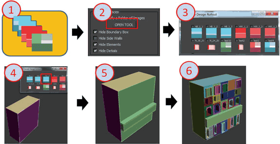
1) First, users look closely at the Facade of building of town which will be generated from now on, generate the division rule of them and the image data such as promotion of windows and save them in the same folder.
2) Use this plug-in, and specify the saved folder.
3) Button group is generated automatically from the saved image.
4) For actual use, choose Quad mesh and then choose one of the image buttons.
5-6) Selected Quad mesh is redivided. The height information depends on Alpha information of image.             Asperity is calculated considering 128 (medium value) as 0. It is necessary to specify an inch base or a meter base. A default is an inch.〔See Figure 1.〕
Figure 1 Workflow

Picture creation has some restrictions. First of all, since the division of Facade is conducted depending on the color difference, when it's anti-aliased, it's divided at each pixel, it should be turned OFF.
Also, the pure color such as black (RGB)=(0,0,0), white (RGB)=(255,255,255) should be avoided because it's used for the material ID and the transformation of window's shape.

 Sample image
Figure 2 which was created by students in the class of Arizona State University is shown. They had never had the experience of use of 3ds Max, but they could generate the building you can see below in an hour.
It seemed they couldn't understand how much should they simplify the building at first because they are not the student of a course in design. After showing some samples for them, they enjoyed working it. Generated 30 buildings approximately were output as a FBX file and imported into UC-win/Road.

Figure 2 Student's work 

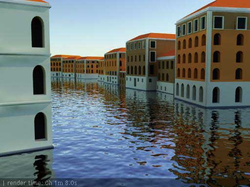
Also the model of the town of Venice I visited in summer for summer workshop was generated using image group of figure 3.

Figure 3 Image group for Facade for the model of town of Venice

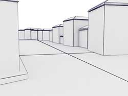
It's possible to create the final model (right figure) in less than 15 minutes from the simple model of figure 4 (left figure).

Figure 4 Town of Venice 

Also the 3D model of book's cover published by Forum8 was created using this tool. (See Figure 5.)

Figure 5 A castle model generated automatically and 12 image groups for it.

 At the end
It became possible to adjust the tool used on your own flexibly by preparing simple pattern image group, and furthermore it's became possible to determine the geometric data of Facade of building and the material by clicking. I'll introduce the texture generation tool which reflected AmbientOcclusion, BakedTextur to show the building better in VR space next time.


Support Topics / UC-win/Road
High Performance Computing on Cloud ServicesTM
About CG Rendering Service

 In the beginning
Super computing cloud (TM) “CG movie service” is an offered service that ray-tracing outputs using POV-Ray which is free 3D graphic software and creates high definition movie file.
Although the greatest characteristic of ray-tracing is to be able to calculate the view of light and material, there is the case to take some hours or some days to create just one image. Although to create a high quality static image, there are more functions to output space information of UC-win/Road into POV-Ray data than before, it could not be used for creating CG movie for the reason that it took much rendering time. By use of super computer, it is possible to save much rendering time and to create a high definition movie which is impossible by usual computers or UC-win/Road.
 Flow of services
For the creation of movie, additional setting for POV-Ray for VR scene created by UC-win/Road is necessary.
After setting, a static image is output by POV-Ray on a trial basis, setting and special effect of POV-Ray are confirmed, and script etc. are adjusted as required. Regarding POV-Ray setting, it can correct script file by editor after outputting and edit the setting flexibly as well. After finishing adjusting setting, each frame of movie is output into POV-Ray, finished AVI is confirmed loosely with AVI output at the same time and frame image. After finishing whole confirmation, rendering by super computing is conducted finally. The rendering result is reconstructed and edited into AVI file, and final delivery is conducted by DVD file etc. finally. 
 Setting of POV-Ray
In POV-Ray, the elements such as object shape, surface characteristic, atmospheric effect, light source, camera position can be adjusted, and confirmation and additional setting on each kind of screen displayed by use of POV-Ray plug-in on UC-win/Road can be conducted as well. Regarding some items that additional setting on UC-win/Road is possible, how to display the setting screen and basic parameter are described this time.

Expression of surface characteristic (material)
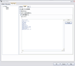
Material information which defines surface material (texture) of object is existing abundantly as a script. These can be edited by "Edit of 3D model" of UC-win/Road, and clicking "texture" tab in POV-Ray tab makes the setting of texture, surface material, transparency etc. possible.
Figure 1 Material setting of a vehicle body

Expression of light source
POV -Ray supports point light source, surface light source and spotlight. When 3D models such as street lamp, light house etc. are used as light source, it can be edited by "Edit of 3D model" dialogue. Clicking each layer on POVRay tab makes the settings of texture, light source and mist possible. Furthermore, by moving and rotating of light source on "movie" setting of model edit screen, it possible to express the action like rotation of light of light house.
Figure2 Setting of light source of light house Figure3 Setting of mist of light house

Expression of water reflection and ripples.
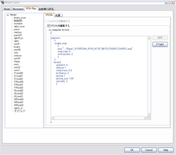
In POV-Ray option, it's possible to express a water surface more reality on UC-win/Road. Settings are edited from "POV-Ray" button which is in "Edit of lake" displayed when a lake is selected and the setting regarding to water reflection and ripples is conducted.

Figure4 POV-Ray setting on water surface and sea

 About outputting of movie
For output resolution and frame rate of POV-Ray movie, 3 kinds of resolutions, LowRes(512*384 15fps)、DVD resolution (720*480 15fps), Blu-ray resolution (1920*1080 24fps) are prepared, and outputting of 6k(5760*2160) movie which is a very high resolution size for a large-sized screen is also possible. It's impossible to  play back with general movie playback software because the capacity becomes very big, 1GB / 1 second in uncompressed state in case of 6k resolution, however, using high effective data compression makes the play back possible.

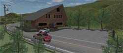
Figure5 Building and material of vehicle are edited and rendered by POV-Ray.
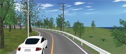
Figure6 Material of vehicle are edited and rendered by POV-Ray.
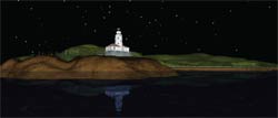
Figure7 Light source, reflection of water etc. are set and rendered by POV-Ray.
(Up&Coming 2011, Late fall issue)

FORUM8