New Products
Work Progress Control Plug-in

Work progress control can be made by measuring the differences between the design data (design value) and point cloud data (actual value).

Price: US$2,800
UC-win
simulation
 Introduction
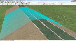
This product operates as a plug-in of UC-win/Road, the difference is measured from the design data (designed value) and the point cloud data (actual measurement value) and each type of report on the work progress control is created. If the design data has already been maintained with LandXML etc., the work progress control report can be made easily by acquiring the work progress in 3D laser sccanning.

It is possible to manage the work progress in an efficient way by comparing and checking (Figure 1) the position from the embankment surface (earth cut surface) designed beforehand in 3DVR.

Click the image for a larger picture.
Figure1 Superposition of
embankment surface and point cloud data

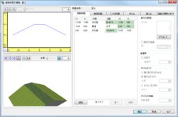
Steps of the work
The tool menu of the main body of Road is extended by installing this plug-in, and a special menu has been added.

About difference calculation
The work flow from the acquisition of design section to the aquisition of measured data is an automatic process, so the work progress control report can be made in an efficient way.
  The main function and feature
About the construction type and structure
They are in accordance with "(3)Specification and civil engineering and construction management standards" of "Common specifications for civil works/ Administration standards for construction etc." established by the Ministry of Land, Infrastructure, Transport, and Tourism of Japan. However they are to be restricted to the earthwork (embankment and earth cut) and road earthwork etc.

About design section
As for the filling shape and cutting ground shape (including the linear), input them by using "Road edit" function which is a function embedded in UC-win/Road itself (Figure 2). It is also possible to import the design data much easily by using LandXML.

Click the image for a larger picture.
Figure 2 Edit of road section 3D laser scanning
modeling service

Standards for work progress control
When limiting to the above-mentioned construction type and structure, measurement item has only height, width (length of slope) and thickness. The standard value can be specified according to the object structure and other standard value such as the internal standard value unique to a specific company can also be defined (Figure 3).
Click the image for a larger picture.
Measurement item Standard value
Standard height ▽ -50
Length of slope l l<5m -100
l≧5m Length of slope -2%
Width w1,w2 -100
Figure 3 Setting of standard value

About the road section
The point cloud data which can be obtained by using 3D laser scanning service of our company etc. and ground level TIN data are applied to the road section. By recognizing the road section (Figure 4), it is possible to obtain a great deal of measuremed data at every specified measurement point in a short time.

Click the image for a larger picture.
Figure 4 Comfirming and editing
the road section
  About work progress control
Create the following work progress control report within the work progress control system used for construct work in line with the "Common specifiction for civil engineering work" established by the Ministry of Land, Infrastructure, Transport, and Tourism of Japan.

Form No Form name
Form 31 Diagram for work progress control
Form 80 Quality / table for work progress control (cover)
Form 81 Lead schedule of the control result
Form 82 List of the control result
Form 84 Diagram for work progress control (Process capability diagram) 
Form 85 Frequency table

Work progress control report can be created in Excel format (supports all versions from 2000 to 2010) (Figure 5, Figure 6) and can also be printed directly (Figure 7). Since it can be made in Excel format, the report can be editted and made to the one according to the contracting agency, hence the versatility of the work progress control report.

Click the image for a larger picture. Click the image for a larger picture. Click the image for a larger picture.
Figure 5 Print preview (Form 31) Figure 6 Excel file (Form 31) Figure 7 Excel file (Form 85)
  Others
Linkage with Photog-CAD
Photog -CAD (Developer: Japan Construction Information Center) can make a 3D model and cross-section and even assessment design document by taking pictures with a digital camera in a disaster site. In this product, the use of the digital camera is assumed as substitution of 3D laser scanner as well by recognizing the ground level TIN data generated from Photog-CAD as work progress.
 Future development
We plan to expand the utilization range of this product by obtaining feedback from users on the expectation of 3D laser scanner's improvement.
(The simulation result of the station premise is shown as an example. This example is a simulation of the congestion situation.)
(Up&Coming '12  Spring Issue)
Back
Back

FORUM8