 |
Necessary of 3D analysis
Many engineers understand the importance of doing the elasto-plastic FEM
analysis for nonlinear behavior of soil. Furthermore, the performance based
design lead to geotechnical analysis using FEM has been increasing. While
"GeoFEAS2D" is designed to conduct 2D analysis, "GeoFEAS3D"
performs 3D analysis such as piles foundation, soil retaining work, effects
of tunnel excavation to surrounding soil, and slope stability. In the series of geotechnical analysis of our company, the Solver was developed by professor Ugai and Fei CAI
at civil engineering, Gunma University. Professor Ugai and Fei CAI have
written various papers and presented the lectures regarding increasing
need of 3D analysis.
Since conducting 3D analysis was considered to be extremely time-consuming
and difficult to do even for engineers, 3D analysis has not been widely
used yet. In respect to that, the Pre-processor (modeling including meshing)
and the Post-processor (visualization and evaluation of result) should
be easy to use and user-friendly. GeoFEAS3D was developed to perfectly
meet these demands. Although 2D analysis has been commonly used in the
past big projects, we believe that 3D analysis is the best solution tool
in future.
Model creation and meshing
In the Pre-processor, we create a model, mesh model, and define stages.
 |
|
 |
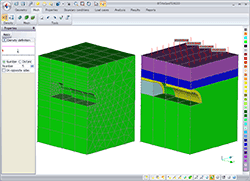
 Tunnel excavation image(Pre) Tunnel excavation image(Pre)
figure below indicates a meshed model (left)/load condition (right)
|
|
 Tunnel excavated process (Pre) Tunnel excavated process (Pre)
|
| The figures below indicate tunnel excavation process. It is very difficult
to consider the effect of excavation on soil at the excavated direction
by using 2D analysis, but we can consider it by using 3D model. |
The Pre and Post processor were developed by Itech (French company) based
on our specifications. The basic process is the same with GeoFEAS2D
Elements library
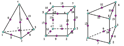
In 2D, soil element is modeled as a plane element, but in 3D we use solid
element. 3D version supports tetrahedral, hexahedral and pentahedral element.
Plane element has two types, one is plate element, and the other is shell
element, but in the first 3D version, it supports only plate element. We
can also define the structural elements (plate element, beam, truss, axial
spring and shear spring element) to consider the interaction between the
soil and the structure.
| Element catalog |
Element type |
Support |
Note |
| Plane elements (Plate element) |
3- node triangle element (linear) |
○ |
Plate element |
| 4-node quadrilateral (linear) |
○ |
Plate element |
| 6- node triangle (quadratic) |
○ |
Plate element |
| 8-node quadrilateral (quadratic) |
○ |
Plate element |
| Solid elements |
4-node 4- surface tetrahedral (linear) |
○ |
|
| 10-node 4- surface tetrahedral (quadratic) |
○ |
|
| 6-node 5-surface pentahedral (linear) |
○ |
|
| 15-node 5-surface pentahedral (quadratic) |
○ |
|
| 8-node 6-surface hexahedral (linear) |
○ |
|
| 20-node 6-surface hexahedral (quadratic) |
○ |
|
| Line elements |
Beam (linear) |
○ |
|
| Truss (linear) |
○ |
|
| Axial spring |
○ |
|
| Shear spring |
○ |
|
| Joint elements |
6-node plane joint element |
○ |
|
| 8-node plane joint element |
○ |
|
| 12-node plane joint element |
○ |
|
| 16-node plane joint element |
○ |
|
Joint element is used for contact between 2 planes.
 |
 Solid elements (tetrahedral, hexahedral, pentahedral) Solid elements (tetrahedral, hexahedral, pentahedral) |
Load and boundary condition
GeoFEAS is a total stress analysis software (not considering soil permeability
for the current version). By considering the hydraulic pressure as nodal
load, it can evaluate the effect of water lever variation on soil. It is
possible to define: nodal load, uniform load, distributed and self-weight
load (including seismic inertia load).Regarding boundary condition, you
can define nodal constrain (horizontal and vertical rollers, fixed, pin,
etc)、Multi points constrain(MPC, hinge), and assign nodal enforced displacement.User
can change the material properties, load and boundary conditions at every
stage (phase)
Processor
The most basic method of stress-deformation behavior analysis of soil is
using elasto-plastic analysis. It is necessary to select proper element
types, constitutive laws, etc.
GeoFEAS has 15 constitutive laws for soil and structure from the simplest
linear elastic constitutive law to elasto-plastic constitutive law. No-tension
material is also available. In the Processor, it is possible to perform
both deformation and stability analysis at the same time by combining stage
and SSR analysis, and to deal with a wide range of soil related problems
such as filled/excavated area, slope stability and bearing capacity, etc.
| Category |
Constitutive law |
Note |
| Elastic |
(1) Linear elasticity |
Isotropic |
| (2) Laminated elasticity |
Anisotropic |
| nonlinear elastic |
(3) Duncan 1 |
Use constant Poisson ration |
| (4) Duncan 2 |
Define volume coefficient |
| (5) D-min |
Technique by CRIEPI |
| Nonlinear |
(6) HD (Hardin-Drnevich) |
|
| (7) RO (Ramberg-Osgood) |
|
| (8) UW-Clay (Ugai-Wakai) |
|
| Elastic-perfectly plastic |
(9) MC (Mohr-Coulomb) |
Associative/nonassociative flow rule |
| (10) DP (Drucker-Prager) |
Associative/nonassociative flow rule |
| (11) MC-DP (Mohr-Coulomb / Drucker-Prager) |
Nonassociative flow rule |
| Elasto-plastic |
(12) PZ-Sand (Pastor-Zienkiewicz) |
|
| (13) PZ-Clay (Pastor-Zienkiewicz) |
|
| No-tension |
(14) Linear elasticity |
|
| (15) Laminated elasticity |
|
Post-processor
In the Post-processor, it is possible to visualize the model, contour,
distributed charts. Some analysis results are shown below.
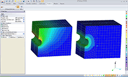
(1)Tunnel excavation: This figure indicates the deformation along excavated
direction
 |
 Tunnel excavation analysis result Tunnel excavation analysis result
(Post of GeoFEAS3D) |
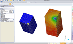
(2)Piles group foundation analysis (1/4 model): This figure indicates the
vertical settlement
 |
 Piles group foundation analysis result Piles group foundation analysis result
(Post of GeoFEAS3D) |
|