|
今回はMultiframeの部材方位機能についてご紹介させていただきます。
1.部材方位(部材座標)
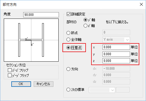
Multiframeでは部材方位を次の5つの方法で設定する事が出来ます(図1)。
 |
 |
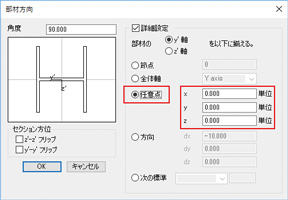
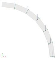
| ■図2 任意の座標点(0,0,0) |
1)全体軸、2)任意の節点、3)任意の(座標)点、4)方向、5)荷重パネル/パッチ。
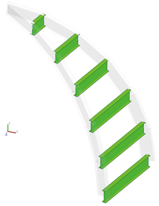
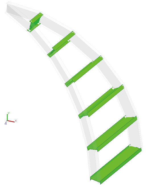
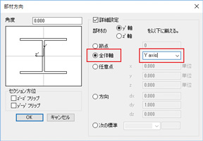
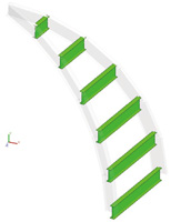
曲面に対して水平に配置したH型鋼を1)全体軸と3)任意の座標点(0,0,0)で設定した場合の図を示します(図2)。
 |
 |
| ■図1 全体軸 |
2.全体分布荷重/部材分布荷重
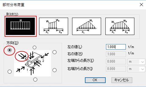
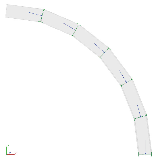
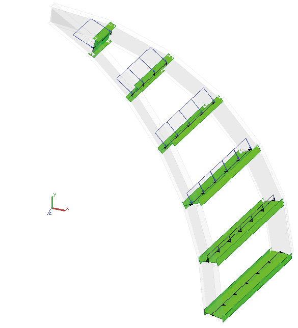
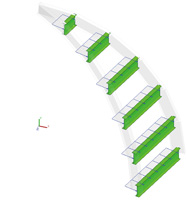
部材の分布荷重には「全体/部材」の2種類がありますが、例えば部材方位を設定し、部材分布荷重を載荷する事によりH型鋼のウェブ面に垂直な荷重を簡単に設定することが出来ます(図3)。
- 鋼材を選択後「荷重メニュー|部材分布荷重」をクリックします。
- ウェブ面に垂直となる方向のラジオボタンをチェックし、等分布荷重として「OK」をクリックします。ウェブ面に垂直な荷重が設定されます。
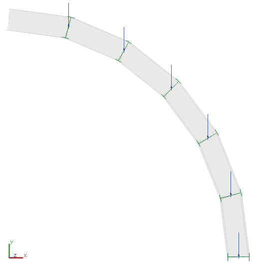
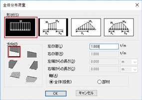
同様に「全体分布荷重」として全体軸-Y(鉛直下向き)を選択すると次のように載荷されます(図4)。
 |
 |
| ■図4 全体分布荷重 |
3.風荷重
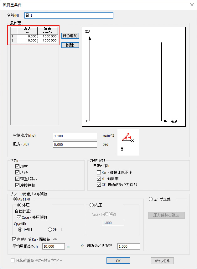
Multiframeには「風荷重」機能として風速・風向等を与える事により自動で受風面積より風圧(風荷重)を算出する機能があります(図5、図6、図7)。部材方位の違いによってこの風荷重も次のように変わります。
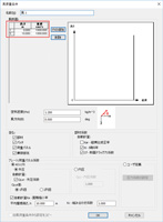
- 風速:100cm/sec
- 風向:全体座標系X+方向(鉛直方向は等分布)
 |
 |
 |
| ■図5 風荷重条件 |
■図6 風荷重-全体軸 |
■図7 風荷重- 任意の座標点 |
4.解析結果
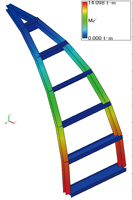
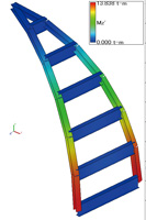
最後に、自重+部材分布荷重+風荷重を組み合わせた荷重ケースを作成して、結果の違いを確認します。曲げモーメントMz’の応力図を以下に記載します(図8、図9)。
 |
 |
| ■図8 Mz’図-全体軸 |
■図9 Mz’図-任意の座標点 |
今回のモデルでは、部材方位を全体軸としたケースのMz’が大きくなりました。
■Multiframe 21.02 日本語版 2017年9月リリース
■開発元:Bentley Systems(Formation Design SystemsはBentley Systemsに吸収合併)
|